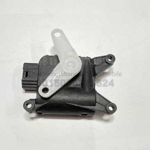
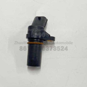
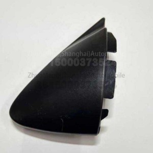
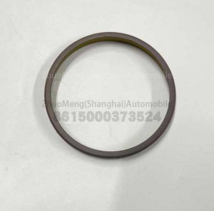
| Products name |
release fork |
| Products application |
SAIC MAXUS V80 |
| Products OEM NO |
C00001660 |
| Org of place |
MADE IN CHINA |
| Brand |
CSSOT /RMOEM/ORG/COPY |
| Lead time |
Stock,if less 20 PCS,normal one month |
| Payment |
TT Deposit |
| Company Brand |
CSSOT |
| Application system |
Power system |
Products knowledge
clutch release fork
technical field
The utility model relates to a structure for separating shift forks of automobile engine parts one by one.
Background technique
The clutch release fork as shown in Figure 1 is an integrally formed sheet metal sheet, the middle part of the metal sheet is wide, and the width gradually decreases toward the front and rear ends, and the left and right sides of the metal sheet are provided with upwardly bent flanges I. , the front end of the metal sheet is provided with a circular hole 2 for installing the fork support mechanism, the rear end of the metal sheet is provided with an upwardly arched circular pit 3 as the contact point of the clutch actuator, and the middle of the metal sheet is provided with a rectangular Hole 4 is used to install the release bearing.
Since the clutch release fork itself has a natural frequency, it is easy to overlap with the natural frequency of the engine during the change of the engine speed, causing resonance and causing the clutch pedal to vibrate.
Utility model content
The utility model aims to optimize the structure of the clutch fork, change its own natural frequency by increasing the mode, and avoid overlapping with the natural frequency of the engine to cause resonance.
For this reason, the technical scheme adopted by the present utility model is: a clutch release fork, which is an integrally formed plate-shaped metal sheet, the middle part of the metal sheet is wide, and the width gradually decreases toward the front and rear ends, and the left and right sides of the metal sheet are wide. Both sides are provided with upwardly bent flanges, the front end of the metal sheet is provided with a circular hole for installing the fork support mechanism, and the rear end of the metal sheet is provided with an upwardly arched circular pit as the contact point of the clutch actuator , a rectangular hole is arranged in the middle of the metal sheet for installing the separation bearing, a first mass block and a second mass block are welded on the top surface of the metal sheet, and the first mass block is welded in the center of the circular hole and the Between the rectangular holes, the second mass is welded between the rectangular holes and the circular pits in the left and right center.
As a preference of the above solution, the first mass block and the second mass block are both rectangular and of equal thickness, the distance between the circular hole and the rectangular hole is greater than the distance between the rectangular hole and the circular pit, and the length of the first mass block is less than The length of the second mass, the width of the first mass is smaller than the width of the second mass. The two mass blocks are of the same thickness, which is convenient for material selection, processing and manufacturing. The two mass blocks are long and short, wide and narrow, and the total mass is almost close. The experimental verification shows that the effect of increasing the modal is more significant.
The beneficial effects of the utility model are as follows: in order to make the separation fork and the natural frequency of the engine not coincide, two mass blocks are added on the top surface of the separation fork, and the two mass blocks are arranged one in front and one behind, respectively located at the two sides of the separation bearing installation hole. On the side, the separation fork increases the mode to change its own natural frequency, and does not resonate with the engine, thereby avoiding the clutch pedal jitter.
Detailed ways
The utility model is further described:
The utility model relates to a clutch separating fork, which is an integrally formed plate-shaped metal sheet, which is symmetrical on the left and right as a whole. The middle part of the metal sheet is wide, and the width gradually decreases towards the front and rear ends. The left and right sides of the metal sheet are provided with upwardly bent flanging I. The front end of the metal sheet is provided with a circular hole 2 for installing the fork support mechanism. The rear end of the sheet is provided with an upwardly arched circular recess 3 as the contact point of the clutch actuator, and the middle of the metal sheet is provided with a rectangular hole 4 for installing the release bearing.
A first mass block 5 and a second mass block 6 are welded on the top surface of the metal sheet, and the first mass block 5 is centrally welded between the circular hole 2 and the rectangular hole 4, and the second mass block 6 is left and right. It is welded centrally between the rectangular hole 4 and the circular recess 3 .
[The first mass 5 and the second mass 6 are both rectangular and of equal thickness, the distance between the circular hole 2 and the rectangular hole 4 is greater than the distance between the rectangular hole 4 and the circular pit 3, and the length of the first mass 5 is less than The length of the second mass 6 and the width of the first mass 5 are smaller than the width of the second mass 6 , which is very significant for increasing the modal effect.


